User Interface
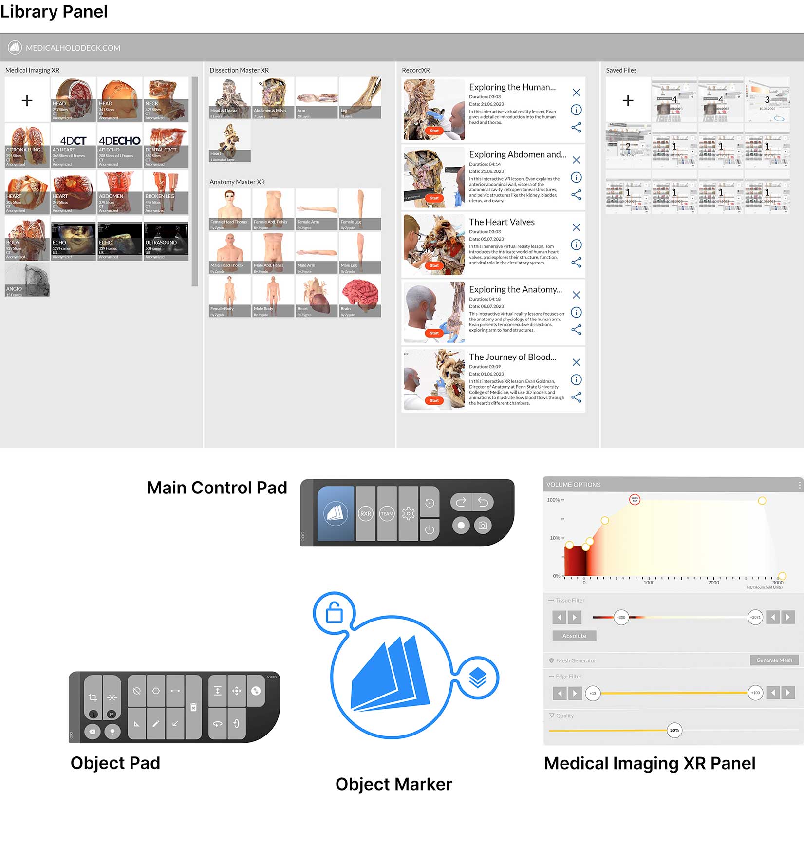
The Medical Imaging XR User Interface consists of the Main Control Pad, the Object Pad, the Library Panel, Medical Imaging XR Panel and Object Marker.
Main Control Pad
The Main Control Pad in the Medicalholodeck interface houses various icons, each representing a unique function.
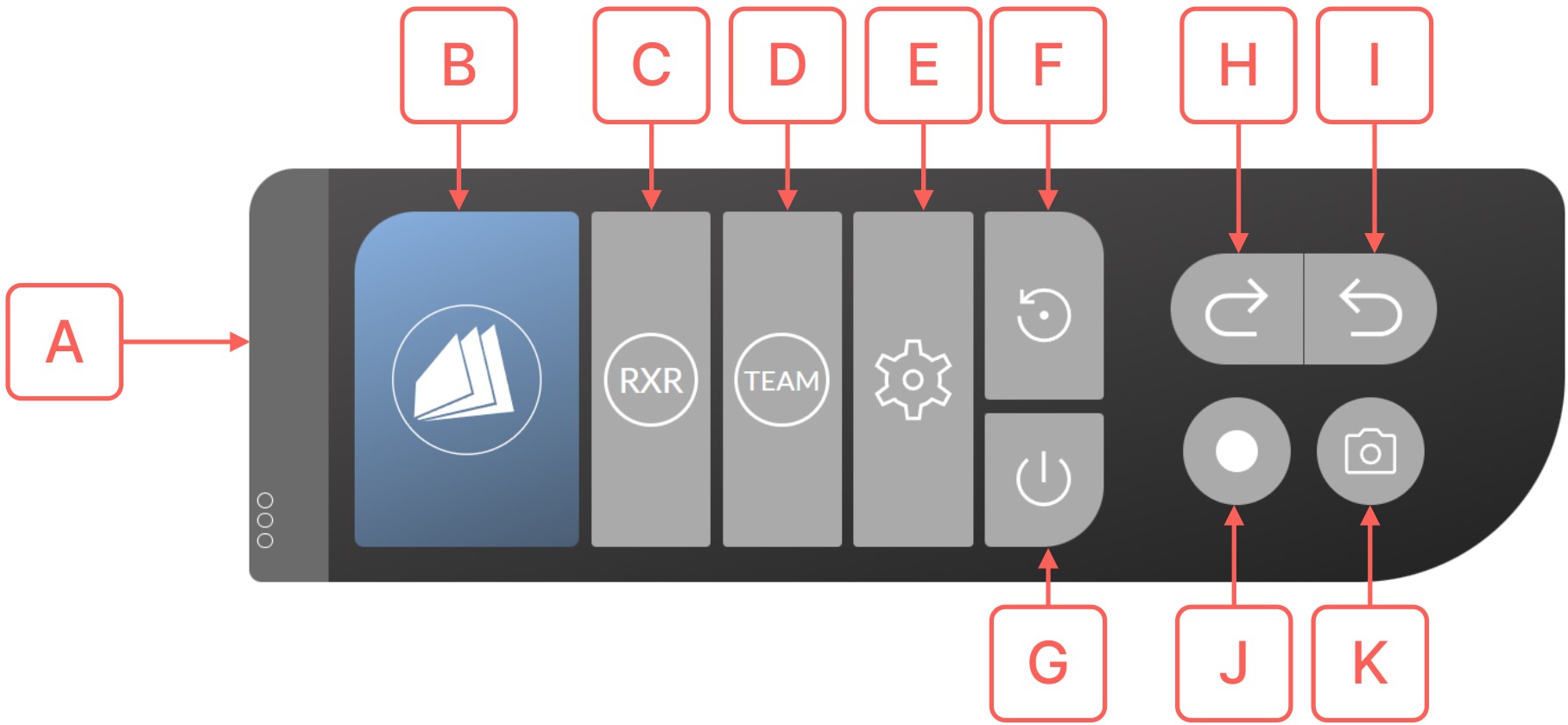
- A Grip
- Utilize the Grip Button to reposition the UI element. Hover over the Grip Button with your laser, then click and hold it by pressing the trigger button on your controller. Move it to your desired location, and then release the trigger button to set the new position. This flexibility allows you to adjust the control pad to suit your preferences.
- B Library
- Click the Library Button in VR to toggle the Library Panel on or off. Simply point your laser at it and press the trigger to make the Library appear or disappear.
- C RecordXR
- Use the RecordXR Button to create immersive VR recordings. Click the RecordXR Button with your laser to start a record. To finish the record, click the same button again. After, the record will appear as a replayable file in the RecordXR Section on the Library Panel.
- D TeamXR
-
Use the TeamXR Button to start collaborative
teamwork. Point your laser at it and press the trigger button to open the TeamXR Panel, which allows you to start, join
and control the VR teamwork experience.
- E Settings
- Use the Settings Button to open Medicalholodeck's Settings. Point your laser at it, and press the trigger button to open the Settings Panel. The Settings Panel is divided into three sections. On the left, you'll find the General options. Next, below are the TeamXR options. And on the right, you have the Recording options. Finally, you can change the tab to Licenses at the top. The licenses screen lets you activate the licenses and check the license expiration date. To close Medicalholodeck's Settings click the same button again.
- F Reset
- Resetting the VR environment is an essential feature that allows you to clear
everything from the scene and return it to its original state. This function
is particularly useful when you want to start a new project, troubleshoot
issues, or simply clean up the workspace.
- G Quit
- To close the application, simply use the Quit Button. Aim your laser at the Quit Button and click the trigger to exit the application.
- H Undo
- Utilize the Undo Button to
reverse your actions within the VR environment. Direct your laser
towards the button and activate it by clicking the trigger,
effectively undoing your most recent action.
An alternative way is to press the A button on your right controller which will also undo the last action. To undo multiple actions, press the button repeatedly, and your actions will be reverted accordingly. - I Redo
- Utilize the Redo Button in VR
to easily redo any actions. Simply direct the laser at the
button and click the trigger to restore the action instantly.
An alternative way is to press the B button on your right controller which will also restore the last action. To redo multiple actions, press the button repeatedly, and your actions will be restored accordingly. - J Capture Movie
- Utilize the Capture Movie Button to record a video of your VR experience. Simply direct your laser at the button and click the trigger to initiate recording. To stop recording, click the same button once more. Your movie will then be accessible as a video file on the Desktop.
- K Screenshot
- Use the Screenshot Button to capture an image of your VR experience. Simply point your laser at the button and click the trigger to take a screenshot, and the image will be automatically saved to your Desktop.
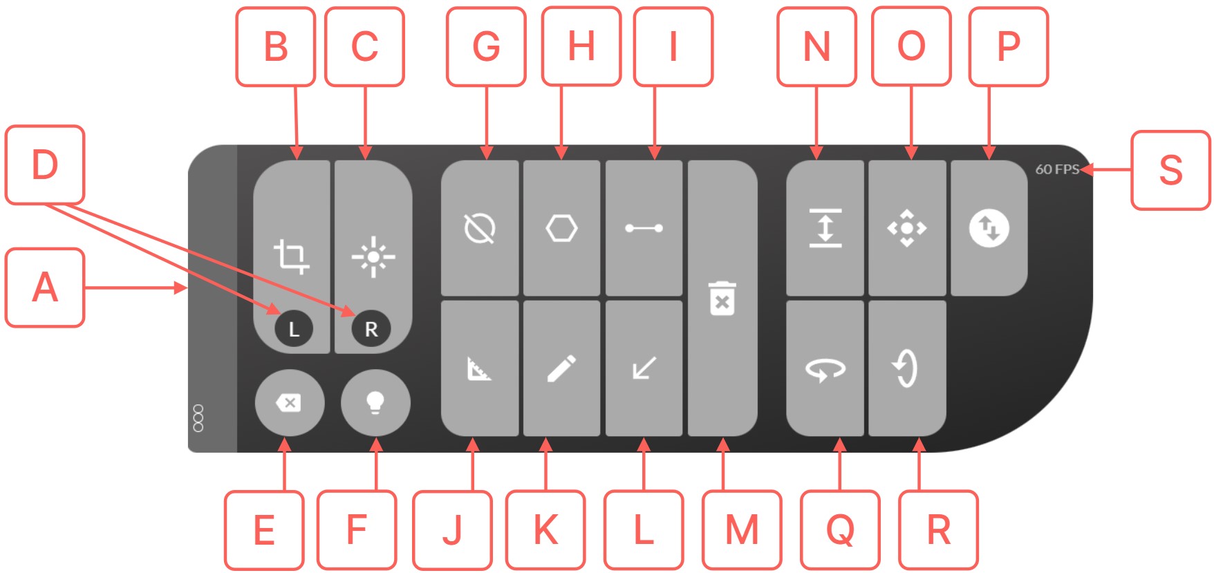
Object Pad
The Object Pad is equipped with a suite of tools designed for dataset manipulation, measurement, and annotation. It becomes available when any dataset is loaded from the Library.
- Turning on the Laser: To activate the Laser, press the Laser On/Off Button. By default, the laser beam will be emitted from your right controller.
- Navigating the User Interface: Point the laser beam directly at any button or item within the interface.
- Making a Selection: To choose or activate a button/item, aim the laser at it and press the trigger on your controller.
- Locate the Switch L/R Button in Object Pad. This button lets you interchange the tools assigned to your left and right controllers.
- Aim the laser at the Switch L/R Button.
- Press the trigger button to toggle between tools. For instance, you can switch from the cutting tool to the laser tool, and vice versa.
Activate the Masking Tool:
- Locate the Masking tool in the Object Pad.
- Aim your laser at the Masking Button.
- Click the trigger button to activate the masking tool.
- Upon activation, the Masking tool icon, appearing as a red ball, will be displayed both below the Object Pad and on your controller.
Apply the Mask:
- Move your controller into the desired position within the dataset.
- Pull the trigger button and hold it down.
- While holding the trigger, move the controller to select the area you wish to mask.
- The selected area can be adjusted by moving the controller around.
- Release the trigger button to finalize your selection.
- The selected area will now be masked, conforming to the mode you have chosen.
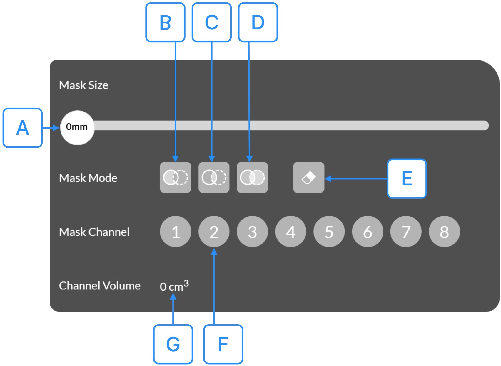
- A Mask Size
- Use the Mask Size Button to adjust the size of the masking tool. Grab it with your laser, pull the trigger, and change the value to the desired size. This will increase or decrease the red ball's size on your fingertip.
- B Masking Mode
-
- Navigate to the Mask Panel and locate the Masking Mode Button.
- Direct your controller's laser pointer at the Masking Mode Button.
- Press the trigger button to activate the Erase mode for the Masking tool, tailored for hiding specific portions of the DICOM dataset.
- To initiate masking:
- Move the controller into the dataset.
- Press the trigger button and glide the controller over the sections you intend to erase.
- Release the trigger button upon completion. The designated region will then become invisible in the VR scene.
- C Isolating Mode
-
- Navigate to the Mask Panel and locate locate the Isolating Mode Button.
- Point your controller's laser at the Isolating Mode Button.
- Click the trigger button to activate the Isolate mode, designed to focus on specific parts of the DICOM dataset.
- To apply the mask in Isolate mode:
- Move the controller into the dataset.
- Hold down the trigger button and guide the controller to highlight the area you wish to isolate.
- Release the trigger button once your selection is made. The chosen area will now be the only visible part of the DICOM dataset, allowing you to concentrate on specific elements for enhanced analysis.
- D Highlighting Mode
-
- Navigate to the Mask Panel and locate the Highlighting Mode Button.
- Aim your controller's laser pointer at the Highlighting Mode Button.
- Click the trigger button to enable the Highlight mode, designed specifically to accentuate certain sections of the DICOM dataset.
- To emphasize areas:
- Move the controller into the dataset.
- Press and hold the trigger button, guiding the controller over the sections you intend to highlight.
- E Undo Masking Mode
-
- Activate the Clean Mode for the Masking tool by pressing the Undo Masking mode Button. This mode lets you reverse previously masked areas in the DICOM dataset.
- To revert a mask, position your controller within the masked areas of your dataset and press the trigger button.
- Gently move the controller to highlight the region you wish to unmask. After selecting the desired area, release the trigger button. The highlighted region will then revert to its unmasked state.
- F Mask Channels
-
- Within the Mask Panel on your VR interface, locate the Mask Channel Buttons.
- Aim your controller's laser pointer at one of the eight available channels.
- Press the trigger button to select your desired channel. This function provides you with eight distinct channels, each designed to mask varying sections of your DICOM dataset.
- With a channel selected, apply the mask to the specific areas. For varied masking effects, simply switch between the channels as needed.
- G Channel Volume
- Use the Channel Volume Measurement Display to check the volume of the masked part of your DICOM dataset on the currently selected channel. The masked volume is displayed in (cm³).
- In the Object Pad on your VR interface, pinpoint the Measure Area Button.
- Aim your controller's laser directly at this button and press the trigger to activate. Upon activation, a black cone materializes on your controller's fingertip.
- Initiate your shape by pressing the trigger, defining the first point. As you navigate your controller, form subsequent points.
- To finalize your shape, guide the cone close to a nearby previously set point. When the CLICK TO CLOSE SHAPE prompt appears, click the trigger. The calculated surface area of the shape will then be displayed in square millimeters (mm²).
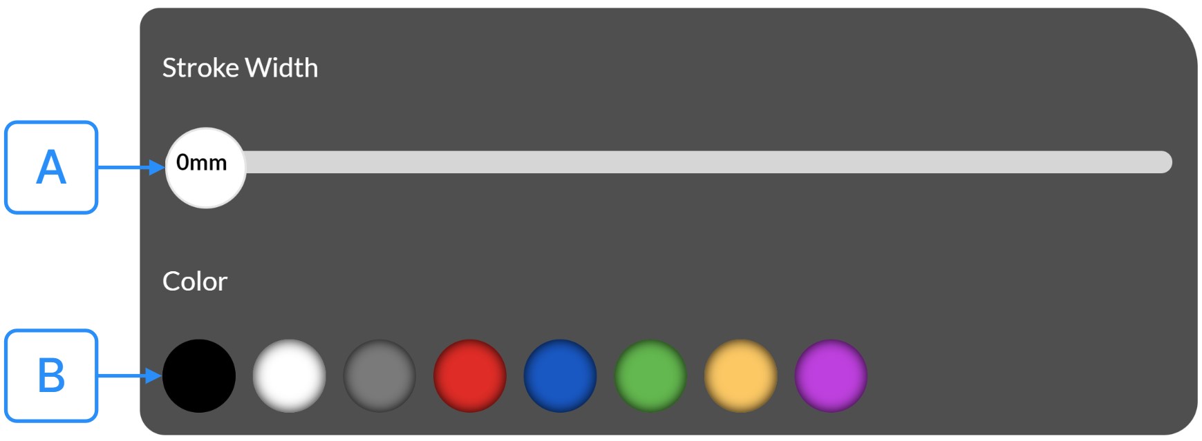
- A Stroke Width
- Use the Stroke Width Button to modify the thickness of the lines you draw. Aim your laser at the button, then pull the trigger and adjust the value to your preferred size. This action will correspondingly increase or decrease the size of the dot on your fingertip, providing you with precise control over the appearance of your lines in the virtual environment.
- B Select Color
- Target the color of your choice and press the trigger button. This action will update the color for the Free Line Drawing tool.
Library Panel
The Library Panel is the central hub for accessing various datasets. Users can locate and load their desired datasets within this Panel for study or work. It's organized into four sections: On the left is the Medical Imaging XR Section, the Dissection Master XR and Anatomy Master XR Sections, followed by the RecordXR and Saved Scenes Sections.
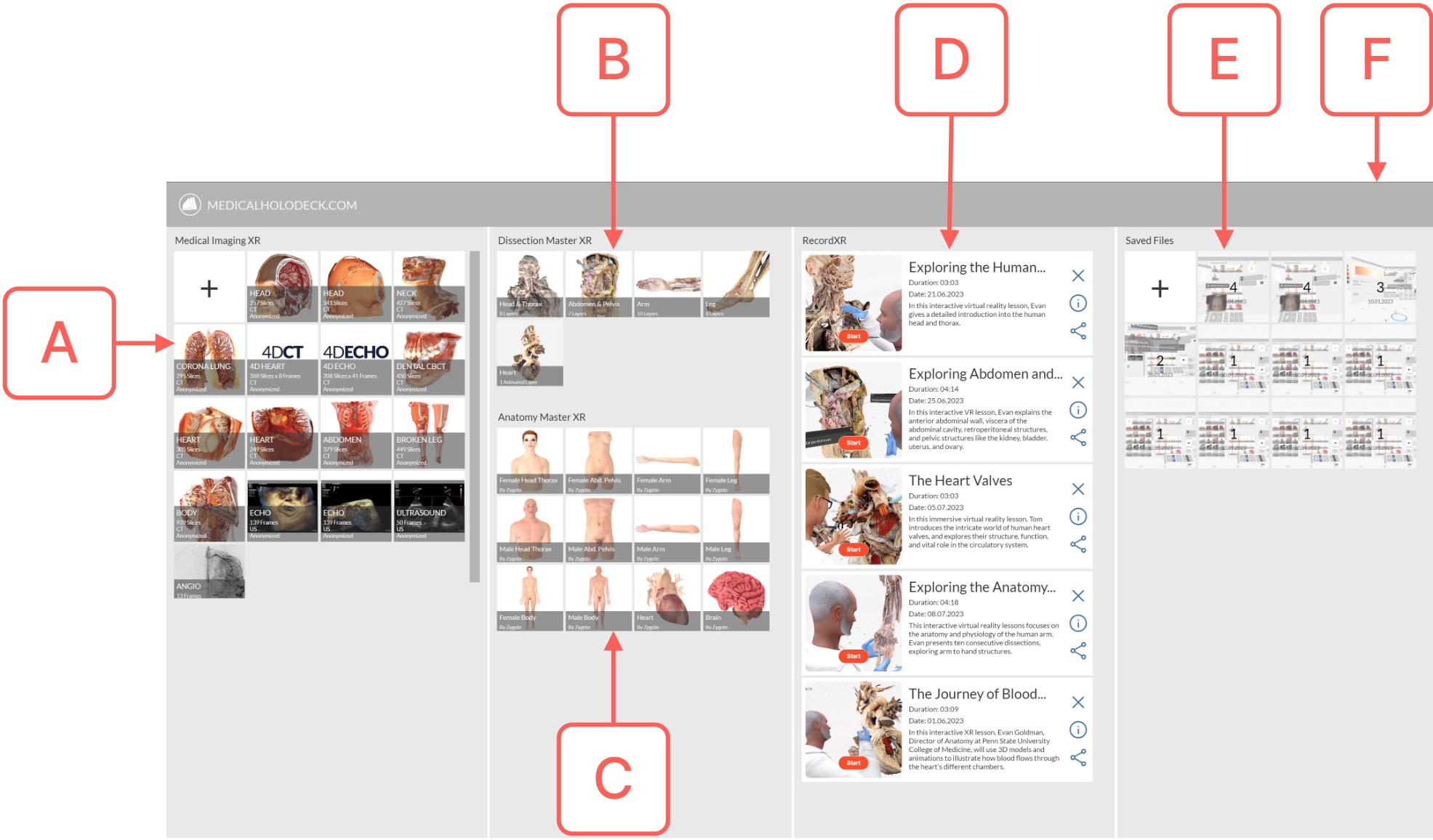
- A Medical Imaging XR Section
- The Medical Imaging XR
Section serves as the dedicated space for
professional medical imaging data management. Here,
users can seamlessly upload their data, activate
datasets for VR visualization, and manage their
content by deleting as needed.
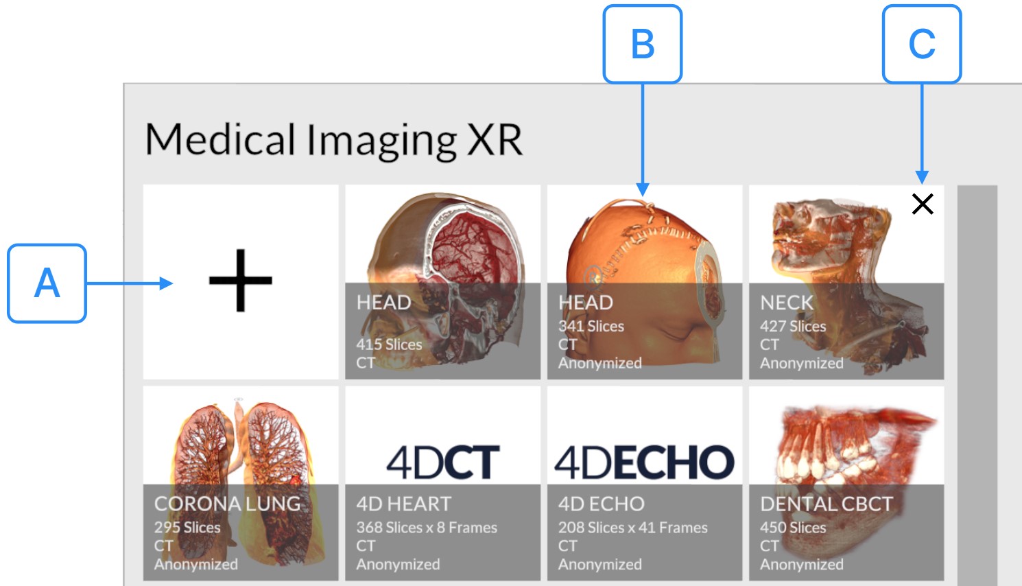
- A Import Data
- Locate and aim your laser at the Import Data
Button, represented by a +
Button. Press
the trigger to access the Import Data
Panel.
-
Local Disk Import
- Choose the Local Disk option at the top of Import Data Panel.
- Navigate and select the desired file or folder.
- Click the Select Button at the bottom. Medicalholodeck will showcase all compatible data.
- You can choose and import multiple files simultaneously.
-
Cloud Import
- Switch to the Cloud Tab at the top.
- Note your 6-digit device ID displayed at the screen's bottom.
- On your computer, opent he web broser and visit https://www.medicalholodeck.com/link
- Enter the previously noted device ID.
- Click Upload from the menu, revealing an upload box.
- Drag and drop your desired files into this box and wait for the upload to complete.
- Back in Medicalholodeck, select the files to add to the Library.
- Click the Import Button at the bottom.
-
- B Activate Data
- Utilize the Activate Data Button to bring a specific dataset to life within the VR environment. Direct your laser towards the button corresponding to your desired dataset and press the trigger button to initiate the activation. Immediately upon activation, the dataset will be rendered and presented in the VR space, allowing for further interaction and examination.
- C Delete Data
- Click this button to remove a dataset from your Library.
- B Dissection Master XR Section
- Dissection Master XR Section is the dissection lab in virtual reality. It consists of layered, fully annotated models based on real human bodies. Use the Activate Data Button to activate and display the dataset in the VR environment. Aim your laser at the desired dataset's button and press the trigger button to activate it. The dataset is immediately displayed in VR. For a detailed walkthrough refer to our dedicated RecordXR Manual.
- C Anatomy Master XR Section
- Anatomy Master XR Section is the three-dimentional human anatomy atlas in virtual reality. It consists of highly detailed male and female 3D anatomy models. Use the Activate Data Button to activate and display the dataset in the VR environment. Aim your laser at the desired dataset's button and press the trigger button to activate it. The dataset is immediately displayed in VR. For a detailed walkthrough refer to our dedicated RecordXR Manual.
- D RecordXR Section
- RecordXR Section is a specialized hub for your spatial recordings. Here, users can review and replay stored records, access in-depth details about each entry, manage storage by deleting records, and export content into RXR files for effortless sharing. For a detailed walkthrough refer to our dedicated RecordXR Manual.
- E Save Scenes Section
- Utilize the Save Scenes
Section to preserve your immersive VR
experience. Saving Scenes enables you to capture and
store the current state of your work within the
virtual environment. This functionality ensures that
you can readily access and continue your work at a
later time, maintaining the exact conditions and
configurations of the saved scene.
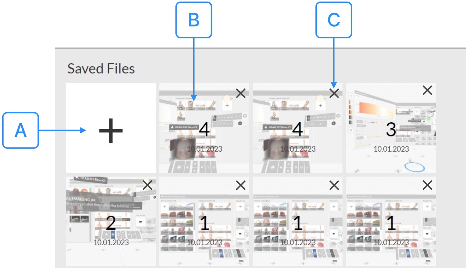
- A Save
- Utilize the Save Button to preserve the current state of the VR Environment. Aim your laser at the + Button and press the trigger to save your work. The Saved Scene will be stored on the right side of the button, and will be identified with a unique Saved Scene ID, the date of creation, and a preview image, allowing for easy access and reference in the future.
- B Load
- Utilize the Load Button to access a previously Saved Scene within the VR environment. Aim your laser at the button corresponding to the chosen Saved Scene and press the trigger button. The scene, with all its preserved conditions and configurations, will be instantly displayed, allowing you to continue your work exactly where you left off.
- C Delete
- Utilize the Delete Button to remove a Saved Scene from the Library. To do so, direct your laser to the top right corner of the Saved Scene Button, where an X Button will appear. Aim your laser at this button and press the trigger. The Saved Scene will be immediately deleted, no longer appearing within the Save Scenes Section.
- F Grip
- Utilize the Grip Button to reposition the UI element. Hover over the Grip Button with your laser, then click and hold it by pressing the trigger button on your controller. Move it to your desired location, and then release the trigger button to set the new position. This flexibility allows you to adjust the control pad to suit your preferences.
Medical Imaging XR Panel
Medical Imaging XR Panel is designed for setting tissue filtering and windowing for DICOMs. Additionally, it provides tools to generate 3D models suitable for 3D printing.
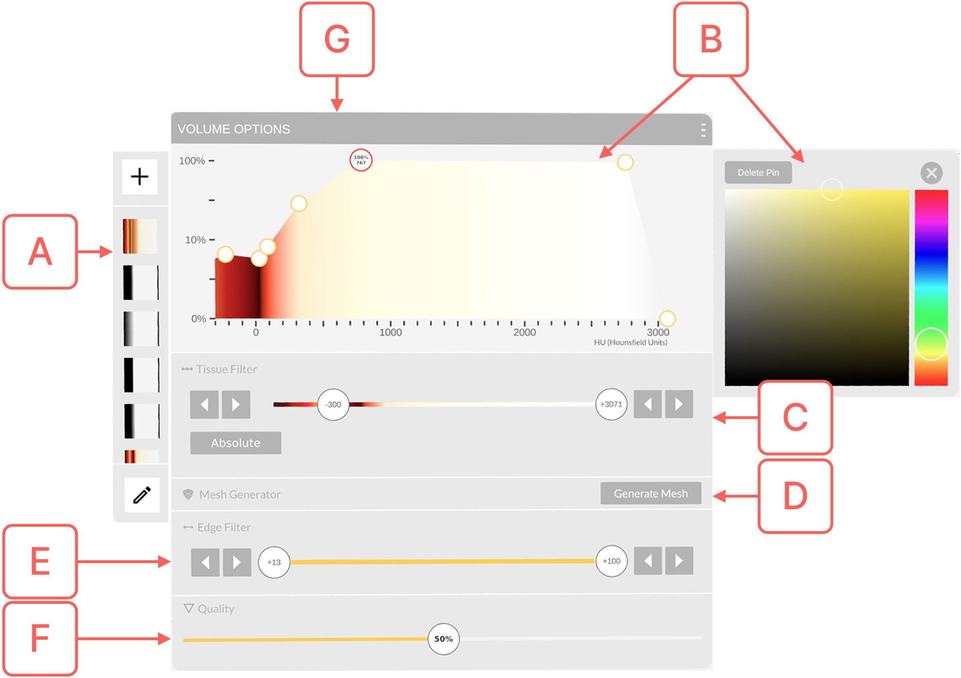
- A Preset Section
-
Utilize the Preset
Section, located on the left side of the
Panel, to manage and store color presets for DICOM
data. Medicalholodeck offers several built-in color
presets, providing you with the flexibility to
select, create, edit, or delete them. This feature
enables full control over color customization,
catering to specific needs and preferences.
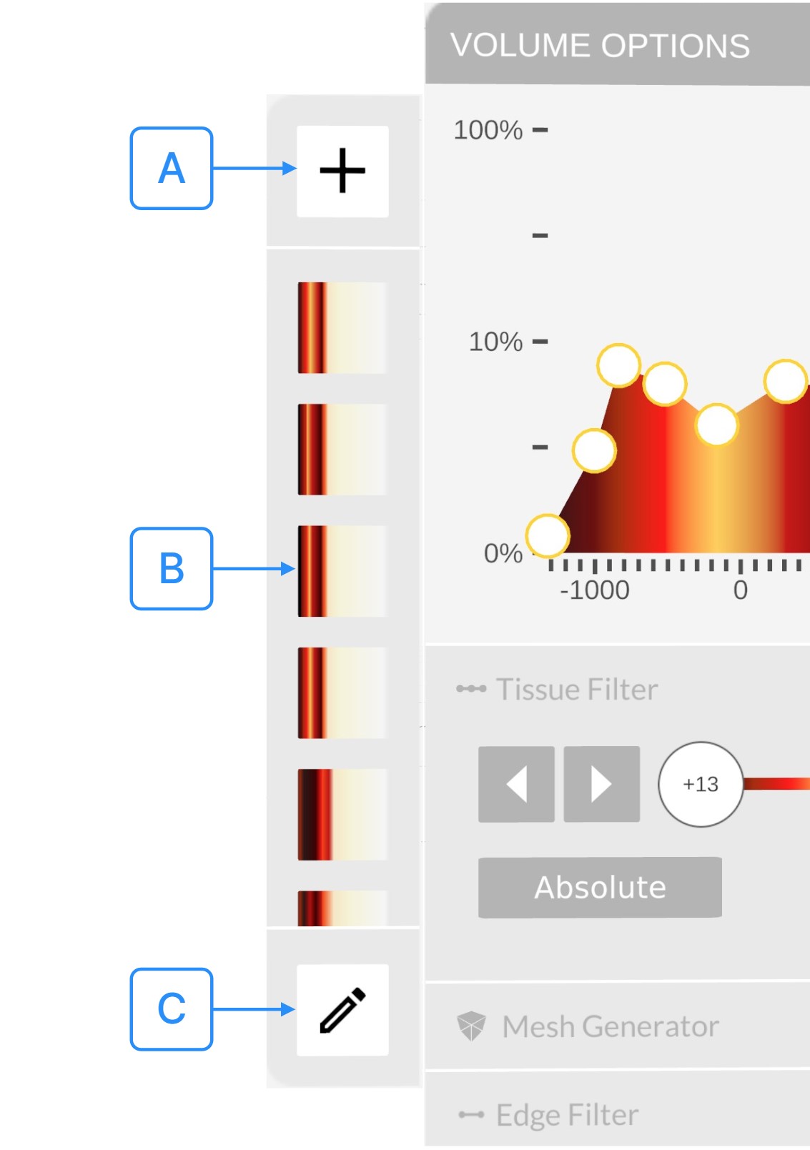
- A Store
- Use the Store Button to preserve your color modifications as a new preset. Direct your laser at the + Button located at the top of the Preset Section, then press the trigger. Your current color settings will be captured and saved as a new custom preset, which will then become visible at the top of the presets list.
- B Preset
- Utilize the Preset Button to load a previously saved preset from the presets list. Simply aim your laser at the desired preset and press the trigger button. The selected preset's settings will be instantly applied to the DICOM dataset, reflecting the stored color configurations.
- C Edit
- Use the Edit Button to modify the presets list. Aim your laser at the Edit Button and press the trigger to activate this mode. Delete preset Buttons will appear. If you wish to delete a preset, direct your laser at the X Button visible on the desired preset and press the trigger to remove it from the list. You can deactivate the edit presets mode by clicking on the Edit Button again.
- B Color Section
- Use the Color
Section located at the top of the Panel
to adjust the transparency and assign colors to
specific Hounsfield Units (HU) using Color
Pins. It
allows you to fully customize the display of DICOM
data.
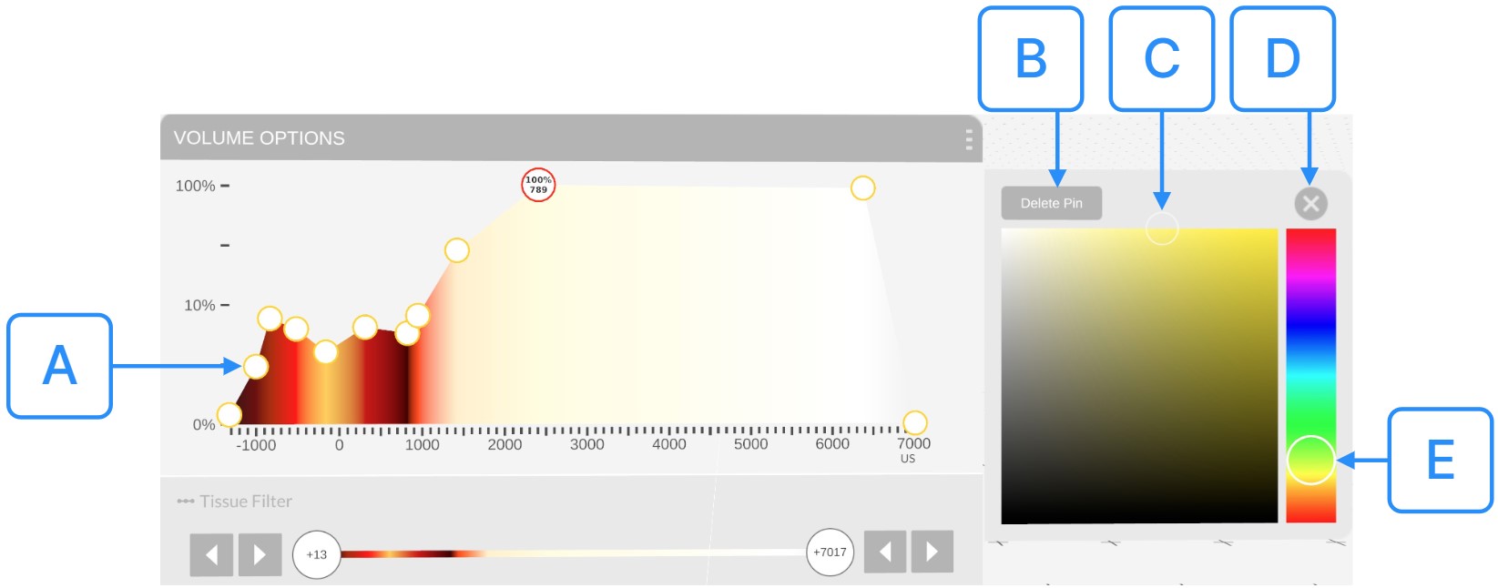
- A Color Pins
- Use the Color Pins to change the transparency and colors for specific Hounsfield Units (HU). The transparency is adjustable from 0% to 100%. To modify this value aim your laser at the color pin of your interest, pull the trigger button to select it, and move the Color Pin vertically. After, release the trigger button to set the color pin in the position. Hounsfield Units (HU) allow you to filter DICOM data based on radiodensity. To assign specific colors to specific HU values, aim your laser at the color pin of your interest, pull the trigger button to select it, and move the Color Pin horizontally. After, release the trigger button to set the color pin in the position. Color Pin is immediately added and the changes are visible on the DICOM dataset.
- B Delete Pin
- Utilize the Delete Pin Button to remove a specific Color Pin from the Color Section. First, aim your laser at the Color Pin you wish to delete and press the trigger button to select it. Then, direct your laser to the Delete Pin Button, located on the right side of the Color Section within the Color Editor Section, and press the trigger to remove it. The Color Pin will be immediately deleted from the Color Section, and the changes will be visibly reflected in the DICOM dataset.
- C Color Picker
- Utilize the Color Picker to modify the color associated with the Color Pin. First, aim your laser at the specific color pin you wish to change, and press the trigger button to select it. Then, direct your laser to the desired color within the Color Picker, located on the right side of the Color Section in the Color Editor Section, and press the trigger to choose it. The newly selected color will be instantly applied to the color pin, and the corresponding update will be reflected in the DICOM dataset.
- D Close Color Editor
- Use the Close Color Editor Button to deactivate the Color Editor Section within the VR Environment. Simply aim your laser at the button and press the trigger. The Color Editor Section, situated on the right side of the Color Section, will become instantly hidden.
- E Hue Selector
- Utilize the Hue Selector to alter the color hue assigned to the Color Pin. Aim your laser at the particular color pin you wish to modify and press the trigger button to select it. Then, direct your laser at the Hue Selector, located on the right side of the Color Section in the Color Editor Section, and press the trigger to choose the desired hue for the pin. The color will be instantly updated in the Color Picker, within the Color Pins Section for the selected pin, and the change will be applied to the DICOM dataset.
- C Tissue Filter Section
- Use the Tissue Filter
Section to window DICOM data. This
section includes the Lower and Upper
Hounsfield Unit (HU) Buttons which allow
you to window DICOM data until the desired body
tissue is visible. You also have the option to
switch between Relative
and Absolute Color Values.
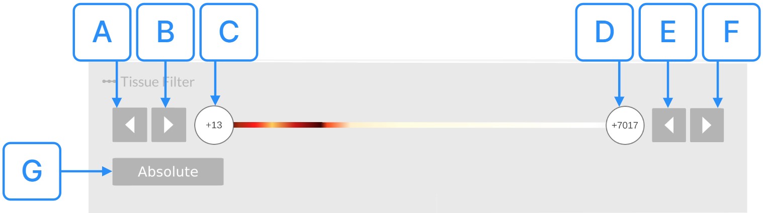
- A Decrease Lower Hounsfield Unit (HU)
- Use the Decrease Lower Hounsfield Unit (HU) Button to decrease the lower value of the Hounsfield Unit range. Aim your laser at the button and press the trigger button. The Lower HU range value is decreased by 1. The DICOM dataset's display is immediately updated accordingly to the new HU range.
- B Increase Lower Hounsfield Unit (HU)
- Use the Increase Lower Hounsfield Unit (HU) Button to increase the lower value of the Hounsfield Unit range. Aim your laser at the button and press the trigger button. The Lower HU range value is increased by 1. The DICOM dataset's display is immediately updated accordingly to the new HU range.
- C Lower Hounsfield Unit (HU)
- Use the Lower Hounsfield Unit (HU) Button to adjust the lower value of the Hounsfield Unit range. Aim your laser at the button, pull the trigger, and move the slider to the left or to the right. After, release the trigger to set the HU value. The lower value of the Hunsfield Unit (HU) range is adjusted and the DICOM dataset's display is immediately updated accordingly to the new HU range.
- D Upper Hounsfield Unit (HU)
- Use the Upper Hounsfield Unit (HU) Button to adjust the upper value of the Hounsfield Unit range. Aim your laser at the button, pull the trigger, and move the slider to the left or to the right. After, release the trigger to set the HU value. The upper value of the Hunsfield Unit (HU) range is adjusted and the DICOM dataset's display is immediately updated accordingly to the new HU range.
- E Decrease Upper Hounsfield Unit (HU)
- Use the Decrease Upper Hounsfield Unit (HU) Button to decrease the upper value of the Hounsfield Unit range. Aim your laser at the button and press the trigger button. The Upper HU range value is decreased by 1. The DICOM dataset's display is immediately updated accordingly to the new HU range.
- F Increase Upper Hounsfield Unit (HU)
- Use the Increase Upper Hounsfield Unit (HU) Button to increase the upper value of the Hounsfield Unit range. Aim your laser at the button and press the trigger button. The Upper HU range value is increased by 1. The DICOM dataset's display is immediately updated accordingly to the new HU range.
- G Relative/Absolute Color Values
- Use the Relative/Absolute Color Values to switch between Relative and Absolute Color Values Mode. In absolute mode, colors are fixed to specific Hounsfield Units (HU). This means that when you limit the HU range using the Lower and Upper HU Buttons, you also limit the visibility of colors associated with those HU values. In relative mode, colors are not directly tied to specific HU values. Instead, they are relative to the current HU window. This means that when you adjust the HU range, the full spectrum of colors will still be visible within the new window, regardless of how narrow it might be. Aim your laser at the button and press the trigger to switch from Absolute to Relative Mode. To change the Color Values Mode again click the same button again. The DICOM dataset's display is immediately updated accordingly to the new Color Values mode.
- D Mesh Generator Section
- Navigate to the Mesh
Generator Section to process your DICOM
data into a 3D mesh. This mesh can be utilized to
craft 3D models suitable for printing or further
analytical exploration.
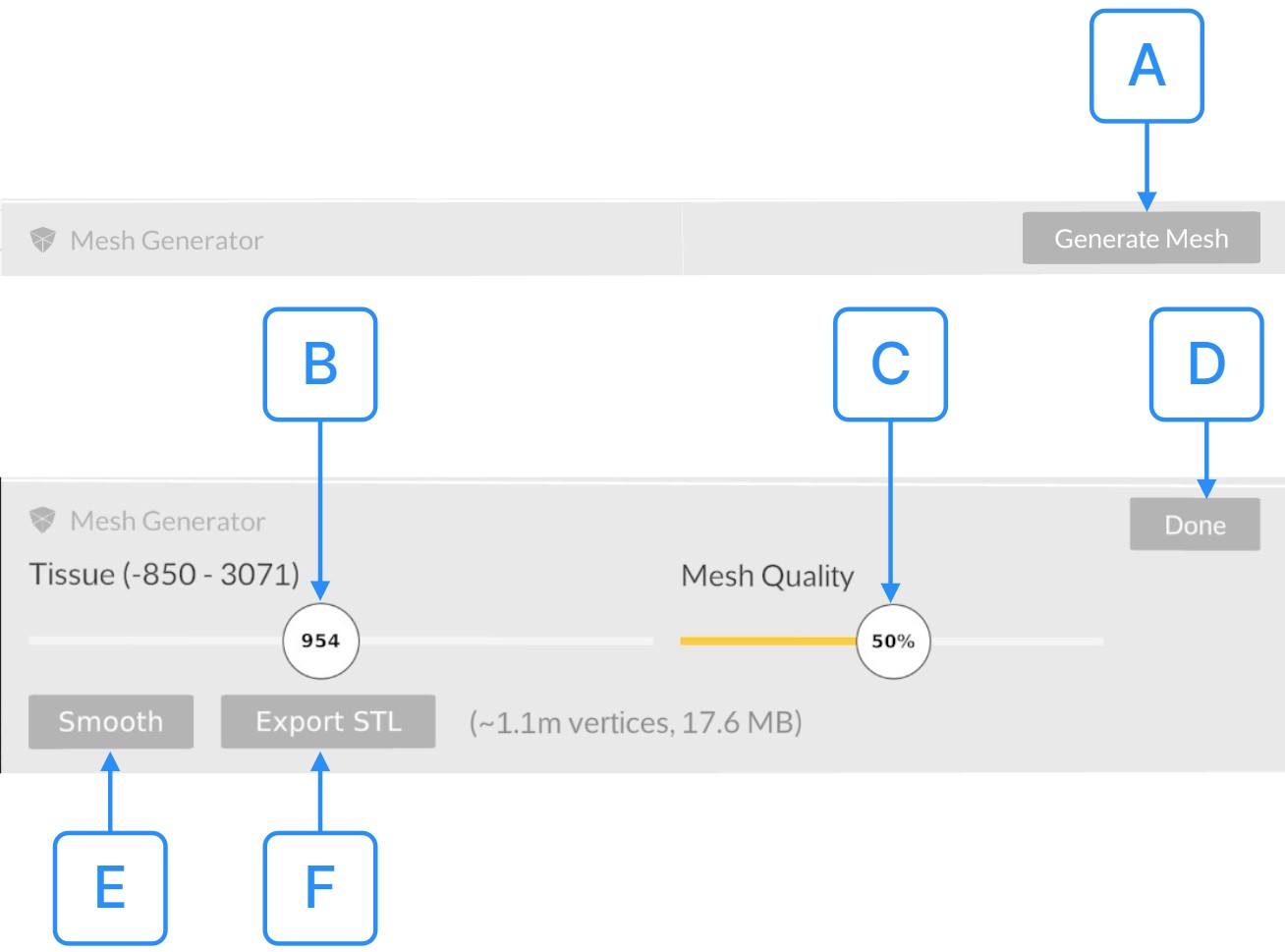
- A Open Mesh Generator
- Activate the Open Mesh Generator to reveal a new set of Mesh Generator options, along with a generated preview of the mesh dataset juxtaposed with the original dataset. Aim your laser at the button and press the trigger, and the updated set of options and mesh datasets will be instantly displayed within the VR Environment.
- B ISO Value
- Utilize the ISO Value Button located on the tissue slider to customize the visibility of specific tissues in the mesh. Aim your laser at the button, pull the trigger, and slide it either to the left or right to make the desired adjustments. The generated preview of the mesh dataset will be immediately updated to reflect the chosen ISO Value. Once you release the trigger, the ISO Value will be set, altering the Hounsfield Unit (HU) value from which the mesh is generated.
- C Mesh Quality
- Utilize the Mesh Quality Button to optimize the generated mesh's quality, enabling a balance between detail level and the size of the resulting STL file. Aim your laser at the button, pull the trigger, and adjust the slider left or right as needed. The mesh dataset preview will instantly update to reflect the chosen quality. Once satisfied, release the trigger to finalize the Quality value.
- D Save Mesh
- Use the Save Mesh Button to finalize the mesh generation process. Aim the Done Button and press the trigger button. The generated mesh is automatically added to the Library Panel and can be loaded into the VR Environment.
- E Smooth Mesh
- Use the Smooth Mesh Button to smooth out the mesh. Aim your laser at the button, and press the trigger button. The generated preview of the mesh dataset is immediately smoothed out.
- F Export STL
- Utilize the Export STL Button to save the results of the mesh generation process. Aim your laser at the button and press the trigger. The generated 3D mesh will be saved as an STL file, directly to your computer's desktop.
- E Edge Filter Section
- Use the Edge Filter
Section to enhance the visibility of
transitions between different tissue densities in
your DICOM data. Filtering based on tissue
homogeneity allows clearer differentiation between
structures. When the filter is adjusted towards the
left, it focuses on more homogeneous tissue. As you
move the filter towards the right, it increasingly
highlights areas where there is a rapid change in
tissue density, such as transitions from soft to
dense tissue.
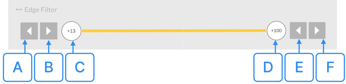
- A Decrease Lower Edge Filter
- Click the Decrease Lower Edge Filter Button to reduce the lower value of the Edge Filter range by one unit. Aim your laser at the button and press the trigger. The Lower Edge Filter range value will decrease by one, and the DICOM dataset's display will be instantly updated to reflect the new Edge Filter range.
- B Increase Lower Edge Filter
- Press the Increase Lower Edge Filter Button to augment the lower value of the Edge Filter range by one unit. Aim your laser at the button and engage the trigger. The Lower Edge Filter range value will be increased by one, and the DICOM dataset's display will be instantly updated to align with the new Edge Filter range.
- C Lower Edge Filter
- Utilize the Lower Edge Filter Button to modify the lower value of the Edge Filter range. Aim your laser at the button and pull the trigger, then move the slider either to the left to decrease or to the right to increase the value. Release the trigger to set the new Edge Filter value. The adjustment is made to the lower value of the Edge Filter range, and the DICOM dataset's display is promptly updated to reflect the new range.
- D Upper Edge Filter
- To adjust the upper value of the Edge Filter range, use the Upper Edge Filter Button. Aim your laser at the button, pull the trigger, and slide it to the left or right to modify the value. Upon releasing the trigger, the Edge Filter value will be set. This adjustment to the upper value of the Edge Filter range will be instantly reflected in the DICOM dataset's display, updating it in accordance with the new range.
- E Decrease Upper Edge Filter
- Utilize the Decrease Upper Edge Filter Button to reduce the upper value of the Edge Filter range by one unit. Aim your laser at the button, then press the trigger. This action will decrease the Upper Edge Filter range value by one, and the DICOM dataset's display will be instantly updated to correspond with the new Edge Filter range.
- F Increase Upper Edge Filter
- Press the Increase Upper Edge Filter Button to raise the upper value of the Edge Filter range by one unit. Direct your laser at the button and activate the trigger. This will result in an increment of the Upper Edge Filter range value by one, and the DICOM dataset's display will be promptly revised to align with the newly adjusted Edge Filter range.
- F Quality Section
- Use the Quality
Section to fine-tune the balance between
the visual quality of your DICOM data and the
application's performance. By adjusting this
setting, you can optimize the display of your data
to match the capabilities of your computer. Whether
you prioritize high-resolution imagery or smoother
performance, this function allows you to customize
your experience to your needs.

- A DICOM Quality
- Use the DICOM Quality Button to adjust the displayed quality of the DICOM data. Grab it with your laser, pull the trigger, and change the value to the desired quality value. This will increase or decrease the visual quality of active dataset in the VR Environment.
- G Grip
- Utilize the Grip Button to reposition the UI element. Hover over the Grip Button with your laser, then click and hold it by pressing the trigger button on your controller. Move it to your desired location, and then release the trigger button to set the new position. This flexibility allows you to adjust the control pad to suit your preferences.
Object Marker
In the VR environment, every loaded dataset is shown by an Object Marker on the floor. This Object Marker serves as an identifier for the active dataset. A blue marker represents an active dataset, a grey marker an inactive dataset. To move datasets, users can interact with the Object Marker. Simply point the laser at the Object Marker, press the trigger, and move the controller to the desired location. Release the trigger once the dataset is positioned as needed.
- A Lock
- The Object Lock feature users to lock a dataset in its position. To lock a dataset point your laser at the padlock icon, which is situated within a small circle on the Object Marker then press the trigger. The padlock will turn red, signifying that the dataset is locked and cannot be moved. To unlock the dataset, click on the red padlock icon again.
Functionality Medical Imaging XR
Supported Hardware
Compatible Headsets
Medicalholodeck is designed to work seamlessly on a wide range of platforms to ensure accessibility and optimal performance. Below is a comprehensive list of supported devices.
Supported VR Headsets:
- META: Quest Pro, Quest 2, Rift S
- HTC VIVE: VIVE + VIVE Pro Series
- VARJO: XR-3, VR-3, Aero
- PICO: Pico 4
- VALVE: Index
- WINDOWS MIXED REALITY HEADSETS: HP Reverb, Dell Visor, Samsung Odyssey, etc.
- MAGIC LEAP: Magic Leap 2
- MICROSOFT: Hololens 2
Compatible PC Hardware
PC-VR version of Medicalholodeck requires a VR-ready Computer. Below are the recommended minimal specifications:
- CPU: i7
- GPU: NVIDIA GTX 1080ti
- RAM: 16GB
Cloud Rendering System Requirements
For Cloud Rendering service on Meta Quest 2 headsets, the following network requirements are recommended:
- Internet connection up/down: 50 Mbps or better
- Wireless networking standard: Wifi 5 or better
How To Connect the Quest 2 to a Computer
To utilize the Medicalholodeck bundle on Quest 2, you'll need to tether the headset to a VR-ready computer. Follow this link for a step-by-step guide on the tethering process: Use Quest Link with Meta Quest headsets.
Licensing
How To Start the Free Trial
Medicalholodeck offers a 7-day free trial, allowing you full access to explore its features. Here's how to initiate your trial:
When you first launch Medicalholodeck, a popup displaying "Start a 7-day trial" should appear. Here's what you need to do:
- Point your laser at the 'Start a 7-day trial' Button within the popup.
- Click the trigger to initiate your free trial.
Should the popup fail to appear, you can manually activate the trial through the VR app's Settings by following these steps:
- Access Settings: Point your laser at the cogwheel icon on the Main Control Pad and click the trigger. This will open the Settings menu.
- Navigate to Licenses: Select the 'Licenses' tab at the top by pointing at it and clicking the trigger.
- Choose the Application: Select the application for which you wish to begin the trial.
- Activate the Trial: Point at the 'Activate Free Trial' Button corresponding to that application, then click the trigger. This will begin your trial period.
How To Activate a License
Activating a License on PC-VR Systems (Tethered)
To activate a license key on a PC-VR System:
- Copy the provided license key to your clipboard.
- Open Medicalholodeck.
- Point your laser at the cogwheel icon on the Main Control Pad and click the trigger to access Settings.
- Navigate to the 'Licenses' tab at the top by pointing and clicking.
- Click on the 'Enter License Key' Button.
- Use the Paste Button to insert the copied license key.
- Confirm by selecting the 'Activate' Button. Your chosen application's license is now activated.
Activating a License on Standalone VR
To activate a license key on a Standalone headset:
- Ensure your headset is connected to the Internet and launch Medicalholodeck.
- Point your laser at the cogwheel icon on the Main Control Pad and click the trigger to access Settings.
- Navigate to the 'Licenses' tab at the top by pointing and clicking.
- Note down the 6-digit device ID displayed at the bottom of the screen; this will be required to link your VR headset to your computer.
- On your computer, open a web browser and go to www.medicalholodeck.com/link.
- Enter the 6-digit device ID into the provided boxes.
- From the left menu, select 'License Management'.
- Choose the application for which you want to activate the license and click on the 'Activate' Button.
- Input your license key in the Panel that appears at the top of the website.
- Confirm the license activation by clicking the 'OK' Button. Your chosen application's license is now activated on your headset.
General
How To Navigate the User Interface
Main Control Pad
With your right controller, access the Main Control Pad situated at the center of your visual field. Point the laser towards the intended item, and a tooltip will emerge, indicating the name of the selected tool for your reference. The Main Control Pad serves multiple functions: it allows you to hide and show the Library Panel, initiate or join a TeamXR session, record movies, and RXR Files, open the Settings Section on the Library Panel, reset the scene, and quit Medicalholodeck. Aim your laser at the desired item and pull the trigger to select it.
Library Panel
Use your laser to access items in the Library Panel, which is centrally located within your field of view.
-
Medical Imaging XR Section
- Contains medical imaging datasets. To activate one, aim your laser at it and press the trigger.
- Use the 'Import Data' Button to bring in data from your local disk or via Medicalholodeck Cloud.
-
Dissection Master XR & Anatomy Master XR Sections
- These sections house anatomical datasets. Activate them in the same manner as datasets in the Medical Imaging XR Section.
-
RecordXR Section
- Store and manage RXR files. Replay, view details, delete from the Library, and export RXR files to your desktop.
-
Saved Scenes Section
- Save scenes by clicking the '+' Button. To revisit a saved scene, aim at one of the tiles storing a saved scene and press the trigger.
How To Use Settings
Aim your laser at the Cogwheel Button in the Main Control Pad to access the Settings Panel. Use the laser to navigate through the options. Select or adjust an option by aiming at it and pressing the trigger button.
-
General Options
- Sync scale across models: Synchronize the scaling of multiple models. When enabled, scaling one model scales all others. Disable for independent scaling.
- Show position markers: Toggle orientation markers for DICOM datasets.
- Show web browser on startup: Decide if the web browser loads upon startup.
- Default quality for volumes: Set default quality for loaded DICOM datasets. Default is 50%.
-
Environment: Choose the app environment.
- 'MHD': Default white space.
- 'AR': Overlay mode for AR headsets.
- 'Dark': Black environment.
-
TeamXR Options
- Join TeamXR with audio: Determines if the microphone is enabled or disabled by default upon joining a TeamXR session. Note that the microphone status can be toggled on or off at any point during the session.
- Sync model panels and selections in TeamXR: When enabled, all users within the current session can view selections made by any user via the Medical Imaging XR Panel. Additionally, everyone will have access to the same active dataset, allowing the entire team to collaborate on it. However, when disabled, each TeamXR user can select and work on their own dataset, applying windowing and tissue filtering independently.
- Color: Adjust your avatar's color in TeamXR.
-
Recording Options
- Offline recording: For videos without skipped frames, typically off.
- Transparent background: Record videos with transparency.
- 4K resolution: Ultra high definition recording. Requires a high-end PC.
- 60 frames per second: Smooth video recording. Requires a high-end PC.
- Record microphone: Toggle audio recording for movies.
- Record microphone XR: Toggle audio recording for RXR files.
-
Licenses Tab
- View and activate licenses.
- Check license expiration dates.
How to Use TeamXR
Use the TeamXR function to start collaborative teamwork.
-
Initiating TeamXR
- Click on the cloud icon representing TeamXR in the Main Control Pad.
-
Creating a Virtual Room
- Aim your laser at the 'Create a Team Button.
- Press the trigger button to generate a unique 6-digit room number.
-
Inviting Team Members
- Share the generated room number with your team.
- Team members join by:
- Aiming their laser at the 'Join a Team' Button and selecting it.
- Entering the provided room number using the built-in keyboard.
- Confirming by selecting the 'Connect' Button.
-
Collaborating on Data
- Load data from the library or upload new data using the '+' Button in the Medical Imaging XR Section.
- Added data is automatically shared with all team members.
Data Import and Handling
Data Importing
Data
Supported Data Formats
The following data formats are supported:
- DICOM Formats:
- 3D DICOM from CT
- 3D DICOM from MRI
- 3D DICOM from CBCT
- 4D Animated DICOM from CT and MRI
- 4D Animated Echocardiography DICOM
- 2D Ultrasound DICOM
- 2D Echocardiography DICOM
- 2D Angiography DICOM
- 3D Model Formats:
- STL
- OBJ
- GLB
- Media Formats:
- Video: MP4, M4V, MPEG, AVI
- Images: JPG, PNG
- Document: PDF
How To Import Data on PC-VR System (Tethered)
- In the Medical Imaging XR Section, point to the '+' Button on the top left of the Library Panel and press the trigger.
- Make sure the 'Local Disk' tab is selected at the top. Use the file explorer to locate your data.
- Point to your desired file or folder and press the trigger to select. For multiple selections, repeat this step or use the 'Select All' Button.
- Once you've chosen your files, click the 'Import' Button at the bottom. Your data will be added to the Library and is now ready for use.
How To Import Data Through Cloud
- In the Medical Imaging XR Section, point to the '+' Button on the top left of the Library Panel and press the trigger.
- Click on the 'Cloud' tab to access the Medicalholodeck Cloud Panel.
- Note the 6-digit device ID displayed on the right side of the Panel.
- On your computer, open a web browser and go to www.medicalholodeck.com/link.
- Enter the 6-digit device ID from your VR headset.
- Click the 'Upload' Button on the left menu. An upload box will appear.
- Drag and drop your desired files (DICOM, STL, OBJ, RXR, PDF, JPG, MP4) into the upload box. Wait for the upload to complete.
- In your VR headset, within Medicalholodeck, select the files you wish to add to the Library. For multiple selections, use the 'Select All' Button.
- Click the 'Import' Button at the bottom to add your data to the Library. Your data is now successfully imported and ready for use.
RecordXR
How to Import RecordXR files On PC-VR System (tethered)
For a detailed walkthrough on using the RecordXR functionality, please refer to our dedicated RecordXR Manual.
How to Import RecordXR files On Standalone VR (standalone)
For a detailed walkthrough on using the RecordXR functionality, please refer to our dedicated RecordXR Manual.
How to Import RecordXR files on Cloud Rendering
For a detailed walkthrough on using the RecordXR functionality, please refer to our dedicated RecordXR Manual.
Data Handling
Dataset
The Active Dataset
The active dataset is distinguished by the Object Marker located beneath it. If the circle appears grey, it indicates that the dataset is currently not active.
To activate a dataset:
- Point your laser at the desired dataset and press the trigger.
- Alternatively, you can click inside the grey circle beneath the dataset to activate it.
- You can also grab the dataset using your controllers; upon doing so, the dataset will automatically become active.
The Hand and Controller Interactions
- Select a dataset from the Library Panel by aiming your laser at its 'Activate Data' Button.
- Move Data: Insert your right hand into the dataset until it's framed in blue. Pull the right controller's trigger to grab, then drag to position. Release to set.
- Scale Data: Insert both hands into the dataset until highlighted in blue. Pull both triggers and move hands apart or together to adjust size.
- Rotate Data: With both hands highlighted in the dataset, pull both triggers and twist your hands to rotate.
How To Use the Laser
The Laser, by default, is on your right controller. Use the Laser to navigate through all windows, panels, sections, tools, and features in Medicalholodeck. To select an item, point the Laser at it and press the trigger. To switch the Laser to the left controller, aim at the 'Switch L/R' Button on the Main Control Pad and press the trigger.
How To Use Cutter
- Activate the Cutter tool from the Object Pad by pointing at it with the laser and pressing the trigger.
- By default, the Cutter is attached to your left hand. To switch hands, aim at the 'Switch L/R' Button on the Object Pad and press the trigger.
- Move the Cutter into the DICOM dataset. As you move the controller, you'll see how it cuts through the data.
- To make a cut, position the Cutter and press the trigger on the controller.
- Multiple cuts can be made on a single dataset.
- To remove a cut, point the laser at the 'x' Button on the top right corner of the cut and press the trigger.
- To turn off the Cutter, press the 'Cutter On/Off' Button again.
How To Use Masking and Segmentation for DICOM
- Activate the Masking Tool from the Object Pad.
- Adjust the tool's size using the slider in the Object Pad. This changes the size of the red ball on your fingertip.
- To mask an area in DICOM dataset, position the red ball over it, hold the trigger, and move your controller.
-
The tool has four modes:
- Isolate, Highlight, and Erase: Modify the mask's visibility.
- Clean: Removes the mask. To undo masking, select 'Clean', hold the trigger, and paint over the masked areas.
- The mask channel function, located below the mode selector, offers eight channels. This lets you mask different sections of your DICOM dataset. Simply change the channel and apply the mask.
- As you switch between channels, the volume measurement updates, showing the volume of the masked parts of your DICOM dataset.
Measure Distances
- Activate the Measure Distance tool from the Object Pad. A black cone will appear on your controller's fingertip.
- Position the cone at the starting point and press the trigger to set it.
- Move the cone to the desired endpoint and press the trigger again. The distance between the two points will be displayed in millimeters.
- To delete a measurement, activate the "Delete" function from the Object Pad. Aim the laser at the measurement you want to remove, then press the trigger.
Measure Angles
- Activate the Measure Angle tool from the Object Pad. A black cone will appear on your controller's fingertip.
- Position the cone where you want the middle point of the angle to be and press the trigger to set it.
- Move the cone to define the endpoint of the first line segment and press the trigger.
- Next, move the cone to define the endpoint of the second line segment. The angle between the two segments will be displayed in degrees. Press the trigger to finalize the measurement.
- To delete a measurement, activate the "Delete" function from the Object Pad. Aim the laser at the angle measurement you want to remove and press the trigger.
Create and Measure a 3D Shape
- Activate the Measure Area tool from the Object Pad. A black cone will appear on your controller's fingertip.
- Position the cone where you want the first vertex of the shape to be and press the trigger to set it.
- Continue moving the controller to define additional vertices, pressing the trigger at each desired point.
- To close the shape, bring the cone close to one of the points. When the tooltip "CLICK TO CLOSE SHAPE" appears, press the trigger.
- The area of the shape will be displayed in mm².
How To Draw on Data
- Activate the Draw tool from the Object Pad. A black dot will appear on your controller's fingertip, and the Free Line Drawing Panel will open below the Object Pad.
- Customize your drawing:
- Thickness: Adjust the line thickness using the 'Stroke Width' button. Grab it with your laser, press the trigger, and slide to your desired size. The dot on your fingertip will change in size accordingly.
- Color: Choose a line color using the 'Select Color' buttons. Aim your laser at your preferred color and press the trigger.
- Begin drawing by pressing and holding the trigger on your controller. Move your hand to draw lines in 3D space. Release the trigger to stop drawing.
- To erase a drawing, activate the "Delete" function from the Object Pad. Aim the laser at the drawing you wish to remove, then press the trigger.
How To Use Arrow Markers
- Launch the Arrow Markers tool by aiming your laser at the 'Mark' function Button on the Object Pad.
- Once activated, an arrow will appear on your fingertip.
- Position the arrow over the area of interest in your dataset.
- Press the trigger to place the arrow marker, highlighting the chosen area.
- To remove a marker activate the 'Delete' function from the Object Pad. Aim your laser at the arrow marker you wish to remove then press the trigger.
How To Delete Objects
- Activate the Delete Objects tool from the Object Pad.
- A red 'x' icon will appear on your controller's fingertip.
- Hover this icon over the object you want to delete.
- Press the trigger button to remove the selected object from the VR space.
How To Move Active Dataset
You have three methods to reposition the Active Dataset within the VR environment.
- Using the Laser
- Aim your laser directly at the dataset or at the Object Marker below it.
- Press and hold the trigger button to grab the dataset.
- Drag it to your preferred location.
- Release the trigger to place the dataset.
- Using Hand Interaction
- Approach the dataset with your right controller until it's framed in blue.
- Press and hold the trigger button to grasp the dataset.
- Move it to the desired spot.
- Release the trigger to finalize its position.
- Using the Move Button
- Direct your laser at the Move Button on the Object Pad.
- Activate it by pressing the trigger button.
- While holding the trigger, reposition the dataset.
- Release the trigger to set the dataset in its new location.
How To Scale Active Dataset
You have two methods to adjust the Active Dataset size within the VR environment.
- Using Hand Interactions
- Insert both hands into the dataset until highlighted in blue.
- Press and hold the triggers on both controllers.
- Move your hands apart or closer together to scale the dataset up or down, respectively.
- Release the triggers to set the new scale.
- Using the Scale Button
- Direct your laser at the Scale Button on the Object Pad.
- Activate it by pressing the trigger button.
- While holding the trigger, slide the controller upwards to enlarge or downwards to reduce the dataset's size.
- Release the trigger to finalize the scale.
How To Move Active Dataset Backward
The Move Backward tool lets you fine-tune the position of the active dataset in relation to your perspective in the VR space:
- Direct your laser at the Move Backward Button in the Object Pad.
- Activate the tool by pressing the trigger button on your controller.
- With the trigger held down, slide the controller upwards to bring the dataset closer or downwards to push it away.
- Release the trigger to set the dataset at the chosen distance.
How To Rotate Active Dataset Horizontally
You can rotate the active dataset horizontally in two ways.
- Hand Interactions
- Insert your hand into the dataset until it's highlighted in blue.
- Press and hold the trigger button to grasp it.
- Rotate the controller horizontally to rotate the dataset to your preferred orientation.
- Release the trigger to set the rotation.
- Using the Rotate Horizontally Button
- Aim your laser at the Rotate Horizontally Button in the Object Pad.
- Activate the rotation mode by pressing the trigger button.
- While pressing the trigger, slide the controller left or right to adjust the dataset's horizontal orientation.
- Let go of the trigger to finalize the rotation.
How To Rotate Active Dataset Vertically
You can rotate the active dataset vertically in two ways.
- Hand Interactions
- Insert your hand into the dataset until it's highlighted in blue.
- Grasp the dataset by pressing and holding the trigger button.
- Rotate the controller up or down to rotate the dataset vertically.
- Release the trigger to lock in the rotation.
- Using the Rotate Vertically Button
- Direct your laser towards the Rotate Vertically Button in the Object Pad.
- Initiate the rotation mode by pressing the trigger button.
- While pressing the trigger, slide the controller up or down to adjust the dataset's vertical orientation.
- Let go of the trigger to set the rotation.
How To Lock/Unlock Dataset
Locking a dataset in the VR environment ensures it remains stationary, preventing unintentional adjustments. This is especially helpful when working with multiple datasets simultaneously.
- To Lock a Dataset
- Select the desired dataset.
- Point your laser at the padlock icon, located within a small blue circle beneath the dataset in the Object Marker.
- Press the trigger button. The padlock will turn red, indicating the dataset is locked and immovable.
- To Unlock a Dataset
- Choose the locked dataset.
- Direct your laser to the red padlock icon.
- Click the trigger button. The padlock will revert to blue, signifying the dataset is now unlocked and can be moved.
How To Remove Active Dataset
- Select the Dataset
- Direct your laser towards the dataset you want to remove.
- Press the trigger button to activate it.
- Remove the Dataset
- Aim your laser at the 'Remove Dataset' Button located in the Object Pad.
- Press the trigger button.
How To Use the Light
- Toggle the Light
- Aim your laser at the 'Light On/Off' Button in the Object Pad.
- Press the trigger button to switch the Light on or off.
- Move the Light with Laser
- Direct your laser toward the Light.
- Press and hold the trigger button to grab it.
- Drag the Light to your desired position.
- Release the trigger to set the Light's position.
- Move the Light with Hand Interaction
- Insert your controller into the Light until it's framed in blue.
- Press and hold the trigger button to grasp the Light.
- Reposition the Light as needed.
- Release the trigger to finalize the Light's new location.
How To Use Medical Imaging XR Panel
- Introduction
- Load your DICOM dataset from the Library.
- The Medical Imaging XR Panel will automatically appear.
- Color Section
- Located at the top of the Panel.
- Adjust transparency levels ranging from 0% to 100%.
- Assign colors to specific Hounsfield Units (HU) using Color Pins. Modify these values by moving the Color Pins vertically for transparency and horizontally for HU values.
- Utilize the Color and Hue Pickers on the right side to alter the color of each pin.
- Preset Section
- Found on the left side of the Panel.
- Medicalholodeck offers various built-in color presets.
- Customize a preset by adjusting or adding color pins.
- Save your settings by clicking the '+' Button, creating a new custom preset.
- Tissue Filter Section
- Includes the Lower and Upper Hounsfield Unit (HU) Buttons to window DICOM data and visualize specific body tissues.
- Toggle Between Relative and Absolute Color Values:
- Absolute Mode: Colors are strictly tied to specific Hounsfield Units (HU). Each color corresponds to a defined HU value, ensuring consistent visualization across different datasets. Adjusting the HU range will display only the colors associated with the selected HU values.
- Relative Mode: Colors adapt dynamically based on the current HU window. The entire color spectrum adjusts and remains visible within the selected HU range, emphasizing variations without being constrained by fixed color assignments.
- Mesh Generator Section
- Generate a 3D mesh from DICOM data for 3D printing or further analysis.
- Edge Filter Section
- Enhance visibility of transitions between different tissue densities.
- Adjust the filter to focus on homogeneous tissue or highlight rapid changes in tissue density:
- Homogeneous Tissue Focus: By sliding the filter to the left, users can emphasize regions of uniform tissue.
- Rapid Density Change Highlight: Shifting the filter to the right will spotlight areas showcasing swift transitions in tissue density, such as the interfaces between muscle and bone.
- Quality Section
- Fine-tune the balance between visual quality and application performance.
- Optimize data display based on your computer's capabilities.
Dataset Library
How To Rename DICOM Datasets and RXR Records
- In the Medical Imaging XR Section, point at the '+' Button on the top left of the Library Panel and press the trigger.
- Access the 'Cloud' tab to open the Medicalholodeck Cloud Panel.
- Take note of the 6-digit device ID displayed on the right for connecting your VR headset to your computer.
- On your computer, visit www.medicalholodeck.com/link and enter the device ID.
- Select either the 'Datasets' or 'RecordXR' Button from the left menu.
- Choose the dataset or RXR file you wish to rename.
- Edit the name in the 'LABEL' input field.
- Click the 'Save' Button to finalize the changes.
Export
How To Make a Screenshot
To capture an image of your VR experience use the Screenshot Button located in the Main Control Pad.
Point your laser at the button and click the trigger to take a screenshot, the image will be automatically saved to your Desktop.
Note: Before capturing a screenshot, ensure that you have sufficient free space on your hard drive.
Insufficient storage may prevent the image from being saved successfully. Regularly check and manage your storage to avoid any disruptions.
How To Create a Video
To record a video of your VR experience, use the 'Record' Button located in the Main Control Pad.
Point your laser at the button and click the trigger to start recording. To stop recording, click the same button again.
The recorded video will be automatically saved to your Desktop.
Note: Before starting a video recording, ensure that you have sufficient free space on your hard drive.
Videos can occupy a significant amount of storage, and insufficient space may prevent the video from being saved successfully. Regularly check and manage your storage to avoid any disruptions.
How To Create and Use Saved Scene
Saved Scenes allows you to save and store scenes for future use, providing a convenient way to arrange your data. You can load multiple datasets from each Medicalholodeck application: Medical Imaging XR, Dissection Master XR, and Anatomy Master XR. This allows you to combine and compare different datasets within the same scene. Once your datasets are loaded, you can manipulate them in various ways. You can cut DICOM datasets, draw on them, place markers, and adjust their size. When your scene is prepared, save it for future use by clicking on the 'Save Scene' Button on the right side of the Library Panel. A thumbnail with a scene number will appear, indicating that your scene has been saved successfully. The next time you open Medicalholodeck, you can load your saved scene by clicking its thumbnail in the Library Panel. All the datasets, objects, and modifications you’ve prepared will be loaded, allowing you to resume your work or start giving a lecture immediately.
How To Create and Use RecordXR
For a detailed walkthrough on using the RecordXR functionality, please refer to our dedicated RecordXR Manual.
How To Create STL File From the DICOM Dataset
- Load your desired DICOM dataset from the Library Panel into the VR environment.
- Once loaded, the Medical Imaging XR Panel will appear.
- Adjust the window levels using the Lower and Upper Hounsfield Unit (HU) Buttons to make the desired body tissue visible.
- Navigate to the Mesh Generator Section below the Tissue Filter Section.
- Click 'Generate Mesh'. A mesh dataset will appear alongside the original dataset, and additional options will be displayed.
- Use the ISO value Button on the tissue slider to set the Hounsfield Unit (HU) value from which the mesh is generated, adjusting the visibility of specific tissues.
- Opt for the 'Smooth' Button if you wish to refine the mesh's appearance.
- Balance detail and file size with the 'Mesh Quality' slider:
- Move left for fewer vertices, resulting in a smaller, less detailed file.
- Move right for more vertices, yielding a larger, more detailed file. The predicted file size is displayed for reference.
- Once content with the mesh preview, click 'Export STL' to save the 3D mesh as an STL file on your desktop.
- Click 'DONE' to add the generated mesh to the Library.
Publication Date: September 2023